Bearing Inserts
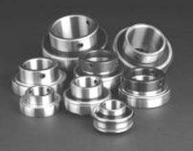
Single row ball bearings with a convex spherical outer diameter generally used with pressed steel or cast iron housings commonly referred to by their registered trade names of SKF "Y-bearings" or RHP "Self Lubes".
- Overview
- Dimensions
- Technical
- Imperial or metric shaft sizes
- Grub screw locking, single or double row eccentric locking or taper sleeve designs
- Tri-lip seal designs available for wet and dirty environments
- Stainless steel inserts to match our Thermoplastic and Stainless steel housings
UC 200 Series inserts
The basic dimensions and load ratings of the UC 200 Series are tabulated below.
- Standard insert features a "dual seal "
- Triple lip seal is denoted by the addition of suffix "-R3"
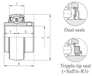
| Bearing insert | d | D | B | C | S | S1 | Locking screw | Dynamic Cr(N) | Static Cor (N) | ||
| in | mm | mm | mm | mm | mm | mm | |||||
| UC | 201S | 12 | 40 | 27.4 | 14 | 11.5 | 15.9 | M5x0.8 | 9550 | 4780 | |
| 202S | 15 | ||||||||||
| 202-10S | 5/8 | ||||||||||
| 203S | 17 | ||||||||||
| 203-11S | 11/16 | ||||||||||
| UC | 201 | 12 | 47 | 31 | 16 | 12.7 | 18.3 | M6x1 or 1/4"-28 | 12800 | 6650 | |
| 202 | 15 | ||||||||||
| 202-10 | 1/2 | ||||||||||
| 203 | 17 | ||||||||||
| 203-11 | 11/16 | ||||||||||
| 204-12 | 3/4 | ||||||||||
| 204 | 20 | ||||||||||
| UC | 205-14 | 7/8 | 52 | 34 | 17 | 14.3 | 19.7 | M6x1 or 1/4"-28 | 14000 | 7880 | |
| 205-15 | 15/16 | ||||||||||
| 205 | 25 | ||||||||||
| 205-16 | 1 | ||||||||||
| UC | 206-18 | 1.1/8 | 62 | 38.1 | 19 | 15.9 | 22.2 | M6x1 or 1/4"-28 | 19500 | 11200 | |
| 206 | 30 | ||||||||||
| 206-19 | 1.3/16 | ||||||||||
| 206-20 | 1.1/4 | ||||||||||
| UC | 207-20 | 1.1/4 | 72 | 42.9 | 20 | 17.5 | 25.4 | M8x1 or 5/16"-24 | 25700 | 15200 | |
| 207-22 | 1.3/8 | ||||||||||
| 207 | 35 | ||||||||||
| 207-23 | 1.7/16 | ||||||||||
| UC | 208-24 | 1.1/2 | 80 | 49.2 | 21 | 19 | 30.2 | M8x1 or 5/16"-24 | 29600 | 18200 | |
| 208 | 40 | ||||||||||
| UC | 209-26 | 85 | 49.2 | 21 | 19 | 30.2 | M8x1 or 5/16"-24 | 31850 | 20800 | ||
| 209-28 | |||||||||||
| 209 | 45 | ||||||||||
| UC | 210-30 | 1.7/8 | 90 | 51.6 | 23 | 19 | 32.6 | M10x1.25 or 3/8"-24 | 35100 | 23200 | |
| 210 | 50 | ||||||||||
| 210-32 | 2 | ||||||||||
| UC | 211-32 | 2 | 100 | 55.6 | 25 | 22.2 | 33.4 | M10x1.25 or 3/8"-24 | 43550 | 29200 | |
| 211 | 55 | ||||||||||
| 211-35 | 2.3/16 | ||||||||||
| UC | 212-36 | 2.1/4 | 110 | 65.1 | 27 | 25.4 | 39.7 | M10x1.25 or 3/8"-24 | 47800 | 32800 | |
| 212 | 60 | ||||||||||
| 212-38 | 2.3/8 | ||||||||||
| 212-39 | 2.7/16 | ||||||||||
| UC | 213-40 | 2.1/2 | 120 | 65.1 | 28 | 25.4 | 39.7 | M12x1.25 or 7/16"-20 | 57200 | 40000 | |
| 213 | 65 | ||||||||||
| UC | 214-44 | 2.3/4 | 125 | 74.6 | 30 | 30.2 | 44.4 | M12x1.25 or 7/16"-20 | 60800 | 45000 | |
| 214 | 70 | ||||||||||
| UC | 215-47 | 2.15/16 | 130 | 77.8 | 30 | 33.3 | 44.5 | M12x1.25 or 7/16"-20 | 66000 | 49500 | |
| 215 | 75 | ||||||||||
| 215-48 | 3 | ||||||||||
| UC | 216 | 80 | 140 | 82.6 | 33 | 33.3 | 49.3 | M12x1.25 or 7/16"-20 | 71500 | 54200 | |
| UC | 217-52 | 3.1/4 | 150 | 85.7 | 35 | 34.1 | 51.6 | M12x1.25 or 7/16"-20 | 83200 | 63800 | |
| 217 | 85 | ||||||||||
| UC | 218-56 | 3./12 | 160 | 96 | 37 | 39.7 | 56.3 | M12x1.25 or 7/16"-20 | 95900 | 71500 | |
| 218 | 90 | ||||||||||
| UC | 220 | 100 | 180 | 108 | 40 | 42 | 66 | M16x1.5 | 122000 | 92800 | |
| 220-64 | 4 | ||||||||||
UCX Series
| Bearing insert | d | D | B | C | S | S1 | Locking screw | Dynamic Cr(N) | Static Cor (N) | ||
| in | mm | mm | mm | mm | mm | mm | |||||
| UCX | 05-14 | 7/8 | 62 | 38.1 | 19 | 15.9 | 22.2 | M6x1 | 19500 | 11200 | |
| 05-15 | 15/16 | ||||||||||
| 05 | 25 | ||||||||||
| 05-16 | 1 | ||||||||||
| UCX | 06-18 | 1.1/8 | 72 | 42.9 | 20 | 17.5 | 25.4 | M8x1 | 25700 | 15200 | |
| 06 | 30 | ||||||||||
| 06-19 | 1.3/16 | ||||||||||
| 06-20 | 1.1/4 | ||||||||||
| UCX | 07-22 | 1.3/8 | 80 | 49.2 | 21 | 19 | 30.2 | M8x1 | 29600 | 18200 | |
| 07 | 35 | ||||||||||
| 07-23 | 1.7/16 | ||||||||||
| UCX | 08-24 | 1.1/2 | 85 | 49.2 | 22 | 19 | 30.2 | M8x1 | 31850 | 20800 | |
| 08-25 | 1.9/16 | ||||||||||
| 08 | 40 | ||||||||||
| UCX | 09-26 | 1.5/8 | 90 | 51.6 | 23 | 19 | 32.6 | M10x1.25 | 35100 | 23200 | |
| 09-27 | 1.11/16 | ||||||||||
| 09-28 | 1.3/4 | ||||||||||
| 09 | 45 | ||||||||||
| UCX | 10-30 | 1.7/8 | 100 | 55.6 | 25 | 22.2 | 33.4 | M10x10.25 | 43550 | 29200 | |
| 10-31 | 1.15/16 | ||||||||||
| 10 | 50 | ||||||||||
| 10-32 | 2 | ||||||||||
| UCX | 11-34 | 2.1/8 | 110 | 65.1 | 27 | 25.4 | 39.7 | M10x1.25 | 47800 | 32800 | |
| 11 | 55 | ||||||||||
| 11-35 | 2.3/16 | ||||||||||
| 11-36 | 2.1/4 | ||||||||||
| UCX | 12 | 60 | 120 | 65.1 | 28 | 25.4 | 39.7 | M12x1.25 | 57200 | 40000 | |
| 12-38 | 2.3/8 | ||||||||||
| 12-39 | 2.7/16 | ||||||||||
| UCX | 13-40 | 2.1/2 | 125 | 74.6 | 30 | 30.2 | 44.4 | M12x1.25 | 60800 | 45000 | |
| 13 | 65 | ||||||||||
| UCX | 14-44 | 2.3/4 | 130 | 77.8 | 30 | 33.3 | 44..5 | M12x1.25 | 66000 | 49500 | |
| 14 | 70 | ||||||||||
| UCX | 15 | 75 | 140 | 82.6 | 33 | 33.3 | 49.3 | M12x1.25 | 71500 | 54200 | |
| 15-48 | 3 | ||||||||||
| UCX | 16 | 80 | 150 | 85.7 | 35 | 34.1 | 51.6 | M12x1.25 | 83200 | 63800 | |
| UCX | 17-52 | 3.1/4 | 160 | 96 | 37 | 39.7 | 56.3 | M12x1.25 | 95900 | 71500 | |
| 17 | 85 | ||||||||||
| UCX | 18-56 | 3./12 | 170 | 104 | 39 | 42.9 | 61.1 | M14x1.5 | 109000 | 82800 | |
| 18 | 90 | ||||||||||
| UCX | 20 | 100 | 190 | 117.5 | 44 | 49.2 | 68.3 | M14x1.5 | 133000 | 105000 | |
| 20-64 | 4 | ||||||||||
UC 300 Series Inserts
| UC | d | D | B | C | S | S1 | Locking screw | Dynamic Cr(N) | StaticCor (N) | ||
| in | mm | mm | mm | mm | mm | mm | |||||
| UC | 305-14 | 7/8 | 62 | 38.1 | 21 | 15 | 23 | M6x1 | 22360 | 11500 | |
| 305-15 | 15/16 | ||||||||||
| 305 | 25 | ||||||||||
| 305-16 | 1 | ||||||||||
| UC | 306-18 | 1.1/8 | 72 | 43 | 24 | 17 | 26 | M6x1 | 27000 | 15200 | |
| 306 | 30 | ||||||||||
| 306-19 | 1.3/16 | ||||||||||
| UC | 307-20 | 1.1/4 | 80 | 48 | 21 | 19 | 30.2 | M8x1 | 29600 | 18200 | |
| 307-21 | 1.5/16 | ||||||||||
| 307-22 | 1.3/8 | ||||||||||
| 307 | 35 | ||||||||||
| UC | 308-24 | 1.1/2 | 90 | 52 | 28 | 19 | 33 | M10x1.25 | 40560 | 24000 | |
| 308-25 | 1.9/16 | ||||||||||
| 308 | 40 | ||||||||||
| UC | 309-26 | 1.5/8 | 100 | 57 | 30 | 22 | 35 | M10x1.25 | 53000 | 31800 | |
| 309-27 | 1.11/16 | ||||||||||
| 309-28 | 1.3/4 | ||||||||||
| 309 | 45 | ||||||||||
| UC | 310-30 | 1.7/8 | 110 | 61 | 32 | 22 | 39 | M12x1.25 | 61750 | 37800 | |
| 310-31 | 1.15/16 | ||||||||||
| 310 | 2 | ||||||||||
| UC | 311-32 | 2 | 120 | 66 | 34 | 25 | 41 | M12x1.25 | 71500 | 44800 | |
| 311-34 | 2.1/8 | ||||||||||
| 311 | 55 | ||||||||||
| 311-35 | 2.3/16 | ||||||||||
| UC | 312-36 | 2.1/4 | 130 | 71 | 36 | 26 | 45 | M12x1.25 | 81600 | 51800 | |
| 312 | 60 | ||||||||||
| 312-38 | 2.3/8 | ||||||||||
| 312-39 | 2.7/16 | ||||||||||
| UC | 313-40 | 2.1/2 | 140 | 75 | 38 | 30 | 45 | M12x1.25 | 93860 | 60500 | |
| 313 | 65 | ||||||||||
| UC | 314-44 | 2.3/4 | 150 | 78 | 40 | 31 | 47 | M12x1.25 | 104260 | 68000 | |
| 314 | 70 | ||||||||||
| UC | 315 | 75 | 160 | 82 | 42 | 32 | 50 | M14x1.5 | 113360 | 76800 | |
| 315-48 | 3 | ||||||||||
| UC | 316 | 80 | 170 | 86 | 44 | 34 | 52 | M14x1.5 | 122850 | 86500 | |
| UC | 317-52 | 3.1/4 | 180 | 96 | 46 | 40 | 56 | M16x1.5 | 132600 | 95600 | |
| 317 | 85 | ||||||||||
| UC | 318-56 | 3./12 | 190 | 96 | 48 | 40 | 56 | M16x1.5 | 143000 | 108000 | |
| 318 | 90 | ||||||||||
| UC | 319 | 95 | 200 | 103 | 50 | 41 | 62 | M16x1.5 | 156000 | 122000 | |
| 319-60 | 3.3/4 | ||||||||||
| UC | 320 | 100 | 215 | 108 | 54 | 42 | 66 | M18x1.5 | 171600 | 140000 | |
| 320-64 | 4 | ||||||||||
| UC | 322 | 110 | 240 | 117 | 60 | 46 | 71 | M18x1.5 | 158000 | 178000 | |
| UC | 324 | 120 | 260 | 126 | 64 | 51 | 75 | M18x1.5 | 175000 | 208000 | |
| UC | 326 | 130 | 280 | 135 | 68 | 54 | 81 | M20x1.5 | 195000 | 242000 | |
| UC | 328 | 140 | 300 | 145 | 72 | 59 | 86 | M20x1.5 | 212000 | 272000 | |
Features of bearing inserts
- Ball bearing with spherical outside diameter
- A wide range or inch or metric bores locked onto the shaft by means of setscrews, eccentric locking collars or taper bush adapters
- Contact seals, flinger seals or triple lip seal configurations
- Considered sealed for life in many applications
Allowable running speeds
The allowable speed for bearing inserts is defined by the quality of support offered by the shaft.
| shaft d (mm) | 200 Series | 300 Series | ||||||
| Shaft tolerance | Shaft tolerance | |||||||
| j7 (h9/IT5) | h7 | h8 | h9 | j7 (h9/IT5) | h7 | h8 | h9 | |
| 12 | 6700 | 5300 | 3800 | 1400 | - | - | - | - |
| 15 | 6700 | 5300 | 3800 | 1400 | - | - | - | - |
| 17 | 6700 | 5300 | 3800 | 1400 | - | - | - | - |
| 20 | 6000 | 4800 | 3400 | 1200 | - | - | - | - |
| 25 | 5600 | 4000 | 3000 | 1000 | 5000 | 3600 | 2600 | 900 |
| 30 | 4500 | 3400 | 2400 | 850 | 4300 | 3000 | 2200 | 800 |
| 35 | 4000 | 3000 | 2000 | 750 | 3800 | 2800 | 2000 | 700 |
| 40 | 3600 | 2600 | 1900 | 670 | 3400 | 2400 | 1700 | 630 |
| 45 | 3200 | 2400 | 1700 | 600 | 3000 | 2200 | 1500 | 560 |
| 50 | 3000 | 2200 | 1600 | 560 | 2600 | 2000 | 1400 | 500 |
| 55 | 2600 | 2000 | 1400 | 500 | 2400 | 1800 | 1300 | 450 |
| 60 | 2400 | 1800 | 1200 | 450 | 2200 | 1700 | 1100 | 430 |
| 65 | 2200 | 1700 | 1100 | 430 | 2000 | 1500 | 1100 | 400 |
| 70 | 2200 | 1600 | 1100 | 400 | 1900 | 1400 | 1000 | 360 |
| 75 | 2000 | 1500 | 1000 | 380 | 1800 | 1300 | 900 | 340 |
| 80 | 1900 | 1400 | 950 | 340 | 1700 | 1200 | 850 | 320 |
| 85 | 1800 | 1300 | 900 | 320 | 1600 | 1100 | 800 | 300 |
| 90 | 1700 | 1200 | 800 | 300 | 1500 | 1100 | 750 | 280 |
| 95 | - | - | - | - | 1400 | 1000 | 700 | 260 |
| 100 | - | - | - | - | 1300 | 950 | 670 | 240 |
| 105 | - | - | - | - | 1200 | 900 | 630 | 220 |
| 110 | - | - | - | - | 1200 | 800 | 600 | 200 |
| 120 | - | - | - | - | 1100 | 750 | 530 | 190 |
| 130 | - | - | - | - | 1000 | 670 | 480 | 180 |
| 140 | - | - | - | - | 900 | 600 | 430 | 160 |
Shaft tolerances
Setscrew inserts are generally mounted with a loose fit for easy installation. For most normal industrial applications the shaft tolerances below should suffice.
| Shaft d | Allowable deviation in shaft diameter (µm) | |||||
| low speed | low-medium speed | medium-high speed | highest speed | |||
| mm | h9 | h8 | h7 | j6 | h6 | |
| over | incl. | max/min | max/min | max/min | max/min | max/min |
| 10 | 18 | 0 / -43 | 0 / -27 | 0 / -18 | +8 / -3 | 0 / -11 |
| 18 | 30 | 0 / -52 | 0 / -33 | 0 / -21 | +9 / -4 | 0 / -13 |
| 30 | 50 | 0 / -62 | 0 / -39 | 0 / -25 | +11 / -5 | 0 / -16 |
| 50 | 80 | 0 / -74 | 0 / -46 | 0 / -30 | +12 / -7 | 0 / -19 |
| 80 | 120 | 0 / -87 | 0 / -54 | 0 / -35 | +13 / -9 | 0 / -22 |
At high speeds or under heavy load, setscrew inserts should be fitted with a tight fit with shaft tolerances indicated below
| Shaft d | Allowable deviation in shaft diameter (µm) | |||||
| medium-high speed | medium-heavy load | high speed | heavy load | |||
| mm | m6 | m7 | n6 | n7 | ||
| over | incl. | max/min | max/min | max/min | max/min | |
| 10 | 18 | +18 / +7 | +25 / +7 | +23 / +12 | +30 / +12 | |
| 18 | 30 | +21 / +8 | +29 / +8 | +28 / +15 | +36 / +15 | |
| 30 | 50 | +25 / +9 | +34 / +9 | +33 / +17 | +42 / +42 | |
| 50 | 80 | +30 / +11 | +41 / +11 | +39 / +20 | +50 / +20 | |
| 80 | 120 | +35 / +13 | +48 / +13 | +45 / +23 | +58 / +23 | |
For bearings with an adapter sleeve an h9 or even h10 shaft tolerance can be used.
Bore tolerance
The insert bore tolerance of inserts is tabulated below
| d | Δ dmp | Kia | Δ Bs | |||
| mm | μm | μm | μm | |||
| over | incl. | high | low | max | high | low |
| 10 | 18 | +18 | 0 | 12 | 0 | -120 |
| 18 | 30 | +21 | 0 | 15 | 0 | -120 |
| 30 | 50 | +25 | 0 | 1 | 0 | -120 |
| 50 | 80 | +30 | 0 | 22 | 0 | -150 |
| 80 | 120 | +35 | 0 | 28 | 0 | -200 |
| 120 | 180 | +40 | 0 | 35 | 0 | -250 |
d - Nominal bore diameter
Δdmp - The deviation of a single plane mean bore diameter of the inner rings
Kia - The radial runout of the assembled bearings inner ring
ΔBs - The deviation of a single width of inner ring
Setscrew tightening torque
The recommended setscrew torques are listed below
| Setscrew size | Tightening torque | ||
| mm | inch | Nm | ibf.in |
| M5x0.8 | No10-32 UNF | 3.16 | 28 |
| M6x1 | 1/4-28 UNF | 34 - 4 | 30 - 35.4 |
| M8x1 | 5/16-24 UNF | 7.8 - 8.3 | 69 - 73.5 |
| M10x1.25 | 3/8-24 UNF | 16.3 - 17.2 | 144 - 152 |
| M12x1.25 | 7/16-20 UNF | 26.5 - 27.4 | 235 - 243 |
| M14x1.5 | 1/2-20 UNF | 33.4 - 34.3 | 296 - 304 |
| M16x1.5 | 5/8-18 UNF | 54 - 54.9 | 478 - 486 |
Overtightening is a common cause of "failure"
Adapter sleeve inserts
After installing the insert, adapter sleeve with locking washer and nut on the shaft , it is usually sufficient to tighten the insert by hand, and then an extra 2/5 - 3/5 of a revolution.
If the insert does not clamp down on the shaft, ensure the adapter size matches the nominal shaft diameter.
Eccentric locking collar inserts
When locked to the shaft in the direction of rotation, the collar will automatically tighten further by the action of the working radial loads. The setscrews are then tightened.
In applications with reversing shafts, a double eccentric locking collar will be required.
High axial load applications
The axial load carrying capacity of the insert will be limited by the quality of fit between insert and shaft.
If a high axial load is to be supported a shoulder should be machine into the shaft against which the insert is fitted. Drilling into the shaft to improve setscrew performance may add unwanted stress multipliers.
In such applications, check the housing is capable of carrying the load in the direction required. The housing tear out strength is not necessarily equal to the carrying capacity of the bearing insert.
Lubrication
Standard bearing inserts are factory filled with a lithium EP2 grease and have an operating temperature range of -20 to +120 °C. In many applications they can be considered "sealed for life".
However, in some applications relubrication is advisable. A guide is tabulated below
| dn value | Environment | Temp C | Relube interval |
| < 40 000 | Clean | -15 to +65 | 6 - 12 months |
| +65 to +100 | 2 - 6 months | ||
| <70 000 | Clean | -15 to +65 | 2 - 6 months |
| +65 to +100 | 1 month | ||
| Any | Dirty | < 65 | 1 week - 1 month |
| > 65 | 1 day - 2 weeks | ||
| Very dirty | Any | 1 day - 1 week | |
| Water splash | Any | Daily/ Constant |
Any good quality lithium or lithium/calcium EP2 grease can be used, and better performance will be achieved with a more modern grease such as a Calcium-sulphonate grease in extremely wet applications.
Associated Products
LUBRICANTS
Ensure an adequate supply of the correct grease to prolong slewring ring life